Pipeline registers
When pipeling we need at access registers between stages. They hold information produced in previous cycle.
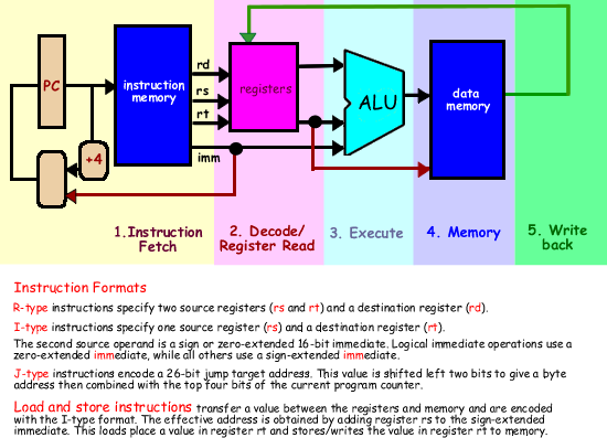
The diagram below shows the flow of information as we progress through the five stages for a MIPS processor.
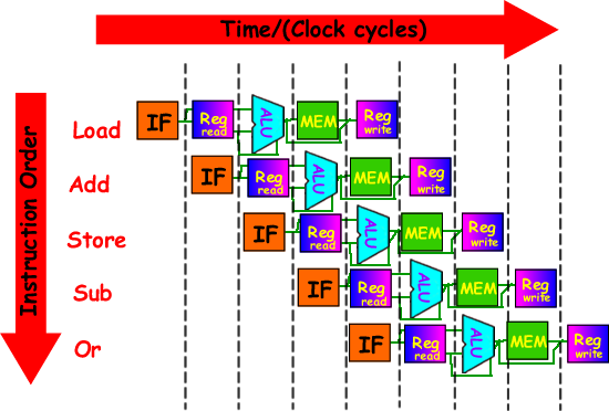
A graphical pipeline presentation
Question
If the time for the various stages are as folllows:
- 100ps for register read or write
- 200ps for other stages
(a) What is the pipelined clock rate?
(a) The clock-rate in computer architecture means cycles per instruction (aka clock cycles per instruction, clocks per instruction, or CPI). It is a term used to describe one aspect of a processor's performance: the number of clock cycles that happen when an instruction is being executed.
We need to work out the timing for each instruction - we can then give the maximum time needed for an instruction. Sometimes you can be asked for the average - but in general we work to the worst-case scenario rule as 'bubbles' occur when we have different timings for instructions... thereby just holding the whole pipeline up.
We can do this in a table. We can then consider what each instruction entails and tot up the time needed.
Instruction |
Instr fetch |
Register
read |
ALU op |
Memory access |
Register
write |
Total time |
lw |
200 ps |
100 ps |
200 ps |
200 ps |
100 ps |
800 ps |
sw |
200 ps |
100 ps |
200 ps |
200 ps |
|
700 ps |
R-format |
200 ps |
100 ps |
200 ps |
|
100 ps |
600 ps |
beq |
200 ps |
100 ps |
200 ps |
|
|
500 ps |
|
The maximum time for an instruction is that for is for 'lw': 800 ps therefore each single cycle of that instruction will be 800 ps.
(b) Compare pipelined datapath with single-cycle datapath.
To work out what happens when we pipeline the datapath we need to construct a timeline.